Behind every LED wall is a chain of electronics that turns a video signal into light. The control system is that chain: it takes the picture from a source, slices it into pieces each cabinet can handle, sends those pieces across a data link, and tells every module exactly which pixels to drive and when. Get the control system wrong and even excellent cabinets will show tearing, colour mismatch, or a black rectangle where a segment dropped out.
The chain has three broad stages. A video processor scales, switches, and composites the incoming sources. A sending card or sending box converts the processed picture into the serialised data stream the wall understands. Receiving cards, one per cabinet or group of cabinets, decode that stream and drive the LED drivers on the module.
Buyers often treat the control system as an accessory to the cabinets and choose it last, on price. That is a mistake. The control system sets the maximum resolution the wall can show, the maximum refresh it can sustain, how gracefully it handles a signal loss, and how easily the whole wall can be re-mapped when the layout changes. These are engineering decisions, not line items.
The control system also determines how the wall behaves day to day. A well-matched sending and receiving pair supports remote monitoring, automatic brightness scheduling, and fault reporting down to the cabinet level. A poorly matched one leaves the operator guessing which module went dark and why.
This guide walks through each stage, the numbers that bound them, and the redundancy and mapping choices that decide how the wall survives in service.
The sending card's key limit is pixel capacity: the total number of pixels it can drive at a given refresh rate and colour depth. Higher refresh and higher grayscale both consume bandwidth, so a card rated for a certain capacity at 60 Hz may carry far less at 120 Hz or with deep processing enabled. Always compare capacity at the refresh rate the wall will actually run.
Receiving cards are rated by how many pixels they can drive and by how many data ports they expose. A card with sixteen ports can fan out to sixteen cabinet runs, which matters when a large wall is wired in a serpentine pattern to keep cable lengths even. The number of receiving cards in a wall is a cost driver, so the layout and the card's port count should be designed together.
Data ports and cabinet wiring follow a simple rule: keep every run the same length and the same number of cabinets so that no cabinet is starved or fed late. Uneven runs cause horizontal tearing, because the cabinets at the end of a long chain receive their frame after the ones at the start.
Backup paths are worth planning at the card level. A receiving card with two inputs can be wired into a ring or a second path from the sending side, so a single broken cable does not blank a section of the wall. On a venue screen that runs every evening, that ring wiring is inexpensive insurance.
Finally, the sending card and the processor must be matched in resolution. If the processor outputs a canvas larger than the sending card can carry, the operator either loses pixels or has to reduce refresh. Confirm the pixel budget of the whole chain before the wall layout is frozen.
| Stage | Device | Main Limit | Design Note |
|---|---|---|---|
| Processing | Video processor | Input count and layer capacity | Sets how many windows can be composited |
| Transmission | Sending card or box | Pixel capacity at target refresh | Compare capacity at working refresh and depth |
| Reception | Receiving card | Pixels driven and data ports | Port count drives cabinet wiring layout |
| Display | Module and driver IC | Refresh and grayscale ceiling | Match driver to control system capability |
| Monitoring | Control software | Network reach and alerting | Enables cabinet-level fault reporting |
The video processor is where sources meet the wall. It accepts HDMI, SDI, or IP streams, switches between them, scales each to the canvas size, and composites layers if the show needs picture-in-picture or keying. A processor with too few inputs or layers forces the operator to add an external switcher, which adds a failure point and a control surface in the rack.
Scaling quality decides how good a non-native source looks. A laptop at 1080p feeding a 4K wall must be upscaled, and a cheap scaler softens text and introduces ringing on sharp edges. A processor with a good scaling engine keeps slides crisp, which is exactly what a conference or control room audience notices first.
Latency matters whenever the wall is used interactively or on camera. A few frames of delay are invisible to a passive audience but obvious in a live camera shot or an interactive installation, where the screen must track a person's motion. Ask for a latency figure in frames at the wall's native resolution, not a general claim of low latency.
Colour management belongs in the processor as well. Gamma curves, colour temperature, and per-cabinet correction let the operator tune the whole wall to a target rather than accepting the default look. A processor that stores several calibrated profiles makes it possible to switch between a bright daytime setting and a dimmed evening setting without re-tuning by hand.
Finally, the processor should be controllable. Network control, preset recall, and an API let the wall integrate with a building system or a show-control console, so the screen turns on with the room rather than needing a separate operator.
| Refresh Rate | Pixel Budget Per Sending Card | Best For | Notes |
|---|---|---|---|
| 60 Hz | Highest capacity | Static signage, slow content | Fewest cards for a given area |
| 120 Hz | About half of 60 Hz capacity | General video and broadcast | Smooth motion for most content |
| 1920 Hz | Moderate capacity | On-camera studio and rental | Baseline for outdoor and studio use |
| 3840 Hz | Lower capacity | Indoor broadcast and fine pitch | Eliminates camera flicker indoors |
| 7680 Hz and above | Lowest capacity | High-speed and slow-motion capture | Used for specialist production work |
Mapping is the process of telling the control system where each cabinet sits in the canvas. On a simple rectangular wall the software can often auto-map, but on a creative shape, a curved wall, or a column wrap, the mapping is manual and needs a drawing. A good wall map, showing cabinet coordinates alongside the physical layout, saves hours every time the wall is serviced.
Redundancy can be built at three levels. A second sending card, wired as a hot backup, takes over if the primary fails. Ring wiring on the receiving side keeps data flowing past a single broken cable. And duplicate power feeds, where the budget allows, protect against a single breaker tripping. Which levels to fund depends on how visible the wall is and how costly an outage would be.
Remote monitoring turns maintenance from reactive to planned. Control software that reports cabinet temperature, voltage, and signal status lets a technician see a degrading power supply before it fails, and lets a multi-site operator check several walls from one dashboard. On a rental fleet or a network of retail screens, that visibility pays for itself quickly.
Firmware and configuration should be managed deliberately. A receiving card fleet benefits from consistent firmware, and a spare card should be flashed and configured to match before it is stored, so a swap during an event is a physical action only, with no configuration step under pressure.
Documentation is the final layer. Record the pixel map, the sending card capacity at working refresh, the data port allocation, and the preset list. That record is what lets a new technician, or the manufacturer's support team, diagnose a fault without rebuilding the whole design from scratch.
Asia Vision Technology supplies LED displays with matched sending and receiving hardware, so the pixel budget, refresh ceiling, and mapping are engineered as one system rather than assembled from unmatched parts. Indoor walls run above 3840 Hz and outdoor walls above 1920 Hz, with remote monitoring available down to the cabinet level.
All products carry CE, FCC, and RoHS certification and ship in 15 to 20 working days with a 3-year warranty. We provide pixel maps, cabinet coordinates, and firmware-matched spare cards so a wall can be serviced quickly anywhere in its life.
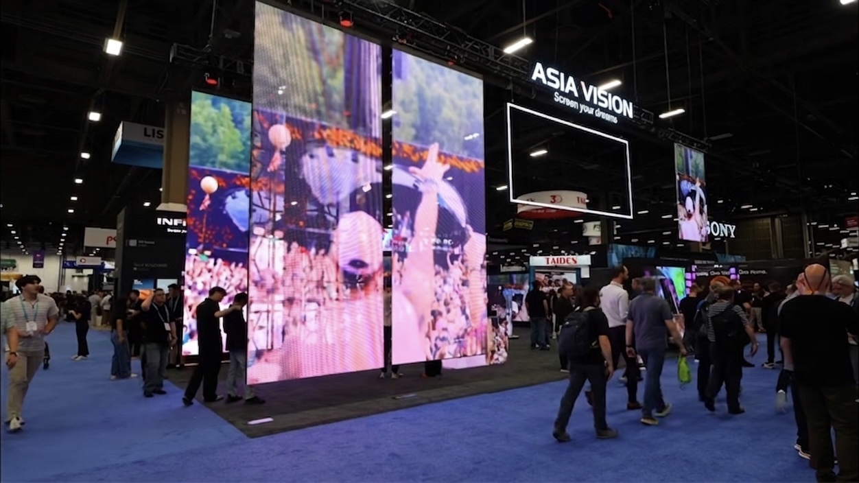
For this requirement our range covers it directly: the COB Z rental series (7680Hz flip-chip) and the COB ZH touring series (sealed, wind-rated).
Related reading: LED Display Content Creation Software Guide 2026
Related reading: LED Display Manufacturer Evaluation Checklist 2026